Hardware 1 - Finding Ground
How to find a device's serial console without a lot of expensive gear.
10 Aug 2017 - David E. Switzer
Intro
Going under the hood with hardware can be fun, but can be somewhat intimidating. Experience has shown us that people tend to think hardware experimentation is harder than it actually is, and this pushes them from jumping into the fun. People often think that expensive JTAG readers or logic analyzers are required, along with confusing software to decode odd/complex protocols. While that is somewhat true (you can get cheaper hardware, and the software isn’t that complex!), there is a simpler way to start learning about hardware: the serial interface.
A lot of devices these days are simply small/embedded Linux systems, and Linux systems will usually have one thing in common: a console. In “olden days”, this would be the monitor and keyboard plugged into the system, allowing you to see it boot, or directly interact with it. Embedded devices don’t tend to have keyboard ports directly accessible (some do!), but they do often have serial/UART ports. This is often the case with other (non-Linux) embedded devices, for the same reason: to allow you to interact with the device, see it boot and/or debug any issues.
Working with a UART/serial port has a few benefits: namely it’s easier to find, and the equipment to interface with it is vastly cheaper. You only need two pieces of equipment besides your laptop: a multimeter (~ 8 - 100+ $USD) and a USB UART adapter (~ 2 - 5 $USD). Essentially, this can be done for around ten to fifteen dollars (USD).
Step 1> Finding a likely candidate.
Typically a serial-only interface (unless obfuscated to attempt to hamper reverse engineering attempts) will be a set of 3 - 6 pins, close together. Sometimes in a row, or 3x3.

The device in this example is a Polycom VVX300 phone. We opened up the device and scanned the board. There was a set of 20 unpopulated pads in a 10x10 format. This seemed like far too many pins to be a serial interface, and if we had more equipment (such as a JTAGulator, a device designed by Joe Grand who also has a fantastic hardware course) to sort through it, maybe.. but this is likely either an expansion port (add on additional board for expanded features?) or some sort of JTAG/etc port.
Looking around more, we find this 3x3 pads (in a convenient “female” factor). This is the only set of obvious pins/pads:
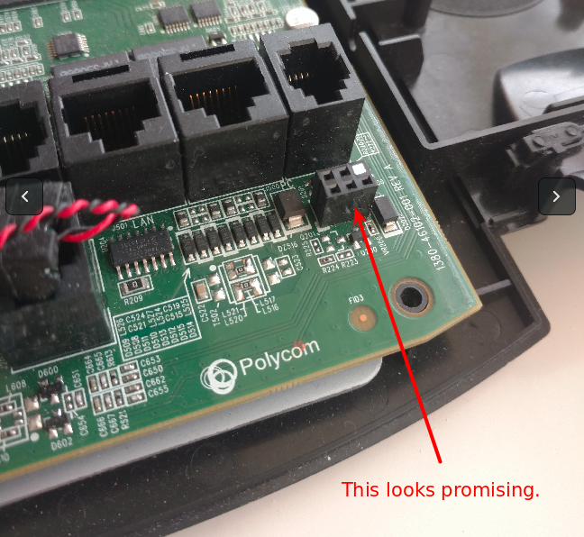
Digging through some manuals, we find that this is used for more complex headsets. And is blatantly called “serial port” in the manual. And is accessible outside of the case without opening it up. So yeah.. cracking the case was..er.. not needed… !@#%.
Now we need to find 3 pins: Ground, Transmit (TX) and Receive (RX). First, the ground.
For the sake of simplicity (namely saving me from fumbling in “The Gimp” trying to draw boxes for an hour), we will use this diagram to explain the pin #s as we will describe:
-------------
| 1 | 3 | X |
| 2 | 4 | 5 |
-------------
Step 2> Find the Ground.
This requires a basic multimeter set to check continuity (this symbol typically looks like an arrow pointing at a vertical line with a line through it, often with a “volume” graphic near it).
First, find a known ground on the device. In general, you want to find a ground as close to your interface as possible. Screws/metal mounts are typically a source of ground. Sometimes you can even find an obvious, large trace that connects to a known ground (such as corner screws on a board), then trace them back to a certain pin on the suspected serial/UART port (not the case here). In a pinch you can use the ground on the power input on the device.
Now, check each pin inside the suspected serial/UART interface until you hear your multimeter beep. Success, we’ve found the ground!
-------------
| 1 | 3 | X |	1 = Ground	3 = ??
| 2 | 4 | 5 |	2 = ??		4 = ??		5 = ??
-------------
Step 3> Find the Transmit (TX) pin.
Time to bust out the UART USB adapter.
WARNING: There is always a chance that plugging random pins into a device that you plug into your computer COULD DESTROY YOUR COMPUTER. We take 0 responsibility, you are ENTIRELY ON YOUR OWN.
That said, most small/consumer devices have low enough power going through them that it won’t impact anything, and using cheap USB UART adapters such as this have an added benefit – they will “lose their magic smoke” and stop working before sending power to your computer, but again – your mileage may vary, the objects in the mirror are closer than they appear, WE ARE NOT RESPONSIBLE.
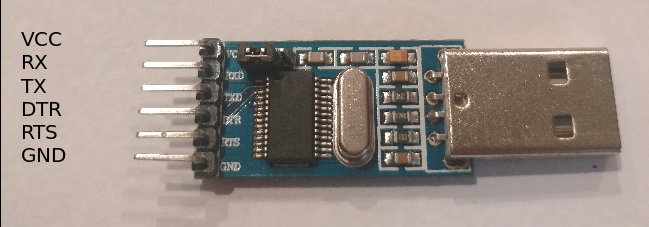
We know what pin to connect to Ground (Pin1 -> GND). Now to find TX (transmit FROM the device), we will plug into RX on the adapter (to receive on the PC).
Note: Do not connect any other pins, especially the VCC pin unless the device specifically needs power from the serial connection. If you’ve plugged it in, or put in batteries – it probably doesn’t need VCC!
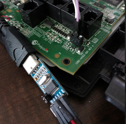
Now you need to determine what “name” the USB UART device is on your system. If you’re on Linux, try dmesg|tail, and look for references to /dev/ttyUSBX (probably /dev/ttyUSB0). After this, you need to run a terminal program to connect to the interface. If on Linux, we recommend “Screen” for simplicity:
screen /dev/ttyUSB0 115200
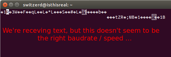
This connects to /dev/ttyUSB0 with a baudrate of 115200. This baudrate is a complete guess. Now, we determine the transmit pin in a very slow, scientific way. By that, we guess a pin on the device, then plug it into RX on the USB UART.
If a device is very “chatty”, you can try any pins to see if you get any text or noise on your terminal program. If you’ve guessed the baudrate right, and you’re lucky – you should see some legible text. If the baudrate is off, you likely will see junk.
If a device isn’t very “chatty”, they tend to talk when booting up. Power off your device, pick a pin to test, connect it to RX on your USB UART, power the device on and watch your terminal. Rinse and repeat until you find a pin on the device that is spewing information on boot.
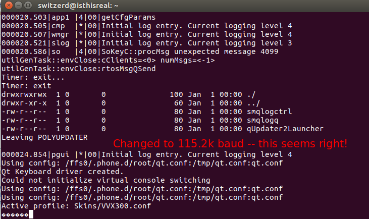
In most cases with equipment (especially consumer devices), the baudrate will be fairly standard. 115200 and 9600 baud are most frequently used, but the other historical standards are possible (300, 1200, 2400, 4800, 19200, 38400 and 57600). Repeat the power off/on test until you see text come up that’s legible.
In the case of the Polycom phone, it was pin 3, and it was 115200 baud.
-------------
| 1 | 3 | X |	1 = Ground	3 = TX
| 2 | 4 | 5 |	2 = ??		4 = ??		5 = ??
-------------
115200 baud, n81
Step 4> Find the Receive (RX) pin.
Note: Not all devices will take input, so your attempts to find a receive pin may be fruitless.
As “RX” is receiving TO the device, we need to plug into the “TX” (Transmit). Typically RX will be a pin off from TX, so a coin flip between pin 2 and pin 4 leads us to try pin 4.
The super complex way to test receive: reboot the device so you see it boot, let it stop sending text… and hit enter. See if the terminal advances a line or two (thus it received and echoed back the CarriageReturn/LineFeed sent by the enter key). If the device accepts input, typically this will show you a response when you’ve hit the right receive pin.
And our first guess worked – pin 4 is receive.
-------------
| 1 | 3 | X |	1 = Ground	3 = TX
| 2 | 4 | 5 |	2 = ??		4 = RX		5 = ??
-------------
115200 baud, n81
Now we have all the information we need to talk to this device via the UART port!
Step 5> .. wait, what is step 5, we figured out the connectivity?!
Step five is basically.. start to play with the device you’re now communicating with. First thing to try is rebooting the device, and watching the boot up process. Some devices will let you interrupt the boot process, and go into some sort of config/debug process or even a Linux/Unix “single user mode”.
Another option is to let it boot and see what prompts it gives you. Non-Linux devices may give you access to a configuration menu/setup program that could be helpful.
Looking for the tools? Here’s a few cheapo eBay examples. Standard disclaimers: We don’t know them, we don’t endorse them, we can’t comment on their quality, and we don’t get a cut from your purchase. These are just inexpensive examples quickly found on eBay:
-
USB UART: CP2102 USB UART Adapter While not the adapter used in the pics above, I’ve bought a ton of these and had a good success rate. Also I appreciate separate pins for 3.3 vs 5v instead of having to remember to switch a jumper.
-
Alternative USB UART: CH340G USB UART Adapter Again, haven’t used this, but it is cheap and will probably work.
-
Multimeter: XL830L Multimeter Never touched this one, just a cheapo that’d work for super basic stuff, such as continuity testing. Probably worth researching ‘em and investing a bit more than this if you think you may be interested in doing more w/ hardware, but if not, this is probably a great entry level multimeter.